There are five main areas of wiring:
- DC wiring from the panels to the rooftop wiring hub, or between the panels if not using a wiring hub.
- DC wiring from the wiring hub on the roof, to the battery bank, which goes through the solar regulator.
- DC control wires that connect your instrumentation to their sensors.
- DC cables that interconnect the battery bank, and connect the battery bank to the inverter.
- AC wiring between the inverter and the existing load center (or sub panel, if using one).
If the inverter does not have terminal
blocks for the AC input/output connections, use crimp-on wire caps when connecting the AC lines to each other in the inverter.
Using twist-on wire nuts, like in a residential electrical connection, leaves the connection subject to loosening/disconnection
due to vibration. If you have to use twist-on connectors, make sure you tape them to the wires securely.
Rooftop Wiring
For the purposes of this article, I will assume you are connecting your rooftop panels in parallel, and that you are
using 12-volt panels (nominal rating). Just like batteries, solar panels come in 12, 24 and 48 volts. Why would you use higher
voltage panels? Two reasons: first, larger panels typically come in higher voltage, so if you want 175+ watt panels you will
be getting higher voltage. Second, higher voltage panels mean less voltage drop on the way to the controller. A technically
superior design would be to use 24 or 48-volt panels and a solar controller that can convert the output voltage to 12-volts.
This allows you to use smaller wiring, or have longer wire runs from the roof to the controller.
With 12-volt panels all wiring is parallel.
You simply interconnect all the + and all – lines. You can do this two ways; daisy chain them from panel to panel, with
the last panel having the wire that comes down to the solar controller, or with a distribution hub on the roof. Use of the
distribution hub helps in several ways. First, each panel’s wire runs directly to the hub, so wiring is easier. Second,
adding a panel later is easier, since you don’t have to modify or lift any of the existing panels. Third, you can use
smaller wire to interconnect the panels, and run a larger wire from the roof down to the controller. If you have panels grouped
together, you can daisy-chain between panels within a group, and then run a single line to the hub. This makes wiring a little
easier.
I prefer to use the distribution hub, but it does increase the cost slightly, and complicates the initial installation
a little. Locate the hub centrally, near the panels. This will minimize the “spaghetti” effect on the roof. You
can then run one larger wire from the hub down to the controller. Look at the voltage drop tables in the Solar Regulator
section to calculate the wire size required. Or, just use #6 wire for the run to the solar regulator, which is sufficient
in almost every case.
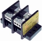
| Double Distribution Block - 4:1 |
|
You can find distribution hubs several places, including at
many Wal-Mart’s in the automotive audio section. Or order them from the internet sources in this article. (Try www.solarseller.com look in section 57, Cat# PDB-175-SIX,
about $29). To build the distribution hub I use a plastic outdoor junction box, which has a removable lid, with a gasket.
It is easy to drill the appropriate sized holes in the sides for routing wires. Use weather-tight wire clamps. I like to use
hubs that have at least four outputs (which you will use as inputs for the wires from the panels). You can usually double
the wires up, if required. You need one hub for + and one for -, or you can buy a dual hub, which is the item above. Position
them in the box so you can tighten the set screws. Epoxy them into the box, when you are satisfied with the layout.
I try to bring the wires in from the sides
of the box that will face the sides of the RV. That way if the entry holes are not perfectly sealed there is less chance of
wind forcing water into the box when driving. I bring the single entrance wire (going to the controller) out the back. To hold the box to the roof, use adhesive caulk compatible with your roof material.
If you have a fiberglass or aluminum roof you can use adhesive silicone caulk. If you have an EPDM rubber roof, or a vinyl
roof use the Dicor adhesive caulk designed for that application – do not use silicone on an EPDM roof, because it will
not stick.
To hold single wires on the roof I use “puddles” of the appropriate adhesive caulk – embed the wires
in the puddle. I put the puddles about every 3 feet along the wire run. Once the caulk sets, add a little to the top. I’ve
been doing this for years, and have never had a wire come loose. For the “bundle” of wires you might have if you
combine the individual wires of multiple panels on the way to the distribution hub (tie wrap them together), use a combination
of caulk and one tie-wrap with a screw slot to secure them. Cover the single screw with caulk. Use caulk alone to secure the
rest of the bundle to the roof.
All rooftop wire should be UV resistant “tray cable”.
Or, you can run conduit if you want, but this is really overkill, and much harder to install. I have very rarely seen conduit
on the roof in an RV installation. I use 10 gauge wire between the panels, or from the panels to the hub, and 6 gauge wire
to run down to the controller. Unless you have an unusual distance from the hub to the controller this is usually sufficient.
Some RV’s have “solar prep” packages. These typically have 10 gauge wire installed by the manufacturer from
the roof to the solar controller location. This is marginal, in most circumstances plus it may not terminate in the location
that you want it. You will have to decide if you want to use this wire, or run another wire that better maintains voltage.
Consult the voltage drop charts and estimate the length of the wire run. In some cases it is easy to add a second wire –
in which case you could run a second 10 gauge wire in parallel to the “solar prep” wire supplied by the manufacturer.
Or you could just run the 6 gauge wire and abandon the manufacturer’s wire. Wire
size and connector quality are particularly important when using an MPPT regulator. Heat and bad wire connections will cause
an MPPT regulator to operate far below its rating, negating any advantage to using it instead of a non-MPPT regulator. One
trick to use if you are putting in your own wire drop from the roof is to use #6-3 with ground. Use the red and black together
(parallel) for the positive run, and white and ground together for the negative run. Even if you don't need
the capacity now, if you are pulling wire it is not much more expensive to use the #6-3. The voltage-drop chart
will tell you what you need to use. Without consulting a voltage-drop chart you are simply guessing. Wire for a 3% or
less voltage drop. That way, even if you do not use a MPPT controller initially, you can swap for one later and be within
the recommended voltage drop for that controller type.
If the input terminals on your solar controller
will not accept the wire size you use, simply clip some of the fine wire strands off until it fits. This won’t affect
anything.
From the solar regulator to the battery bank I usually use 6 ga wire, depending on the length of the run. There is
a fuse installed in this line. I use automotive ATO fuses or "Maxi" fuses instead of the glass fuses usually supplied in solar
installation kits or with some regulators. They are easier to install, and easier to insert fuses. It is also easier to "pull"
them if you want to service the lines. If you need more capacity than the #6 wire will give you and don't want to use heavy
cable, you can run the #6-3 like I describe above. Fuse each of the "positive" lines individually.
Battery - to - Inverter Wiring
Your inverter manufacture will provide a chart that will tell you the requirements for wire sizes from the battery bank
to the inverter. They will also specify the fuse size required on the positive line at the battery. You need to follow the
manufacturer's instructions carefully. If you underwire this connection you can start a fire or damage the equipment. Don't
cheap out and delete the fuse. The fuse protects your RV from fire if the inverter malfunctions. You definately don't want
your RV burning down.
Lets assume you are using a 2000 watt inverter. In this case, you will use 2/0 or 4/0 cable to connect from the battery
bank to the inverter, depending on the distance. The shorter the distance, the better, but your inverter can be as much
as 10-12 feet (of cable run) from the battery. Use the heavier 4/0 cable if you are even close to the rollover point between
the cable sizes. Bigger is always better when it comes to cabling the battery/inverter.
The 300-400amp fuse (use the size specified by the manufacturer) should be mounted within 18" or so of the battery. You
can mount it in an appropriate fuseholder, or you can bolt it directly to the positive post of the battery if you have no
method to mount a fuseholder. The fuseholder is preferred.
The wires to the inverter will put out a magnetic field that can affect electronics in the RV - especially the AM band
on the radio, and potentially TV's. Usually, this is not a problem, but it can be. To minimize the potential for this interference
you can twist the cables around each other, or parallel them together. It is usually easier to parallel them together, using
a tie-wrap every foot or so. This results in the magnetic fields cancelling each other out.
Information on how to build cables, types and sizes of fuses, sources for fuses, appropriate lugs to use, and how to
lay them out is in The Truck Electrical Center section of this website.
Interfacing
to Your Load Center
There are some major considerations in
interfacing to the load center that can drive the entire system design and complexity.
The first is determining if you will use an inverter with a transfer
switch rating that matches the capacity of the main breaker in your load center. In other words, are you using a 30 amp-rated
inverter in a 30 amp RV, or using a 30 amp-rated inverter in a 50 amp RV? There is a major difference in system design and
capabilities. If you are not installing a sub panel, it is best to match the rated capacity of the inverter transfer switch
to the RV AC capacity – a 30 amp inverter with a 30 amp RV; a 50 amp inverter with a 50 amp RV. You pay more for a 50
amp inverter, but you will make it up on ease of installation and system design considerations.
The second major consideration is if you will install a sub
panel for the inverter loads. Use of a sub panel to isolate the inverter loads is technically the best design, but practical
considerations may lead you away from this implementation. The use of a sub panel isolates the lower power circuits that you
will supply inverter power to, from the high amperage circuits that are impractical to support with a battery bank. Typically,
these high amperage circuits are the air conditioner(s), the electric hot water heater, the converter (if it is left in the
system) and any other high-amperage appliance circuits, including the refrigerator. In addition, the 120-volt lighting circuits
are usually left in the main panel. Circuits that are moved to the sub panel
are typically the wall outlets and the microwave. This includes the entertainment
center, since this is typically driven off wall outlets.
AC Wire Types
RV manufacturers all use regular house
wire from the AC feeds in RV’s. Type NM wire is solid copper wire and is sufficient for use. A better wire is boat wire,
which is stranded and tinned. Stranded wire stands up to vibration better, but is much more expensive. It is required for
marine use by Coast Guard regulation. I usually recommend use of standard house wire because it is easy to find.
Plus, your rig is already wired with it, so upgrading just a portion of it is not usually justified. When using any solid
wire in an RV make sure you crimp the connections (do not use wire nuts). This will prevent vibration from loosening the connection,
which it can, over time. If you decide to use wire nuts anyway, at least tape them to the wire.
Grounding
Unless your inverter manufacturer states otherwise, you may directly ground the house battery bank to the chassis. All
other DC system ground will be carried back through the chassis ground. There is a DC ground point on the inverter itself.
It must also be grounded to chassis at any convenient point. Make sure you use the proper size wire.
Some inverter manufacturers specify that the battery bank not be directly grounded to the RV chassis. All DC grounding
is to originate at the inverter and the DC loadcenter. If your inverter manufacturer specifies this method of grounding, you
need to follow it.
Neutral Bonding
Most high-power inverter chargers
intended to be hardwired have an AC neutral-to-ground bonding system. This bonds neutral to ground while inverting, and disconnects
neutral from ground while on shore power. The purpose is to satisfy code requirements that specify neutral-ground bonding
can only occur at one location. The utility power feeding the inverter will have neutral bonded at the electrical panel; therefore
the inverter must not have neutral bonded when on shore power. This is the same
reason that RV’s NEVER have neutral bonded to ground in the RV electrical panel. Neutral and ground must float
in an RV electrical system. When doing the AC wiring to the inverter, do not connect the AC input
neutral directly to the AC output neutral; use the separate connection lugs provided. Otherwise, you will circumvent the neutral
bonding system.
I mention this mainly because installation of some inverters can cause an anomaly when hooked to shore power circuits
protected by a GFCI or AFCI. That is, the GFCI may be tripped by the inverter neutral-to-ground bonding relay. This occurs
because the GFCI relay that detects a neutral-ground short (potentially a dangerous condition) is “faster” than
the inverter neutral bonding relay. When shore power is connected, power passes through the (normally closed) inverter bonding
relay before it can be activated (opened), and back to the GFCI. This causes the GFCI to detect the neutral-ground short and
disconnect the power. All this happens in milliseconds, and is typical in “driveway boondock” situations where
you may be plugged into a friend’s garage outlet, or on an outdoor receptacle (including those 20 amp outlets in RV
pedestals) – all of which are required to be GFCI protected. There is no way to circumvent this, other than to find
a non-GFCI outlet. Look at the garage door opener outlet; code does not require that to be GFCI-protected (but it may be anyway).
Note that some inverters have provision to circumvent the neutral bonding system. Do not do this unless you know what you
are doing.
Installing a Sub Panel
When retrofitting a sub panel to an existing system the two major issues
are locating the panel, and having enough wire length in the existing circuits that you want to move to reach the new panel
location. The sub panel is typically fed by a 30 amp breaker in the main panel, and is fed by 10 ga. wire. It can be located
anywhere that is practical to reach – in a 5th wheel it is often located in the main storage compartment.
It is unusual to have enough slack in the wire to reach the new box location – even if the sub panel is co-located with
the main panel. If you are lucky, all the wires will feed the main panel from
below, and you will be able to pull them down and install the sub panel below the main panel. Often, the circuits have to
be extended. If the main box has enough room you can simply use crimp on connectors and add the required wire to reach the
sub panel. You have to extend all the wires, including the neutrals and grounds. Often, the main panel does not have enough
room in it to splice in the new wire extensions – in that case you have to add a junction box near the main panel that
contains the spliced wires. Make sure that you crimp the wires – do not use wire nuts.
The sub panel should be sized to handle the number of circuits
that you need to move. If you can, get a panel that has at least one extra circuit. It does not matter if the sub panel is
the same brand as what is already in your RV. Usually a 60 or 70 amp panel containing four to six circuits is sufficient.
When shopping for panels you will have a choice of “main breaker” or “main lug” panels. Main breaker
panels contain a breaker controlling power to the entire panel. Main lug panels have connectors for the input wires but no
breaker for the input. They depend on a properly sized breaker in the main box to control over-current conditions. The easiest
box to use is a main lug box, because it has separate neutral and ground buss bars (or provision for an add-on ground buss
bar). Main breaker boxes do not usually have separate buss bars, but have space on a common buss bar for both neutral and
ground wires. You must maintain a separate neutral and ground in RV electrical systems. Neutral and ground wires are never
joined on the same buss bar, as in residential wiring. When hooking up your wires,
make sure that the neutrals are attached to the insulated buss bar.
An additional advantage to using a sub
panel is that shore power is not being fed through the inverter transfer switch for your high-draw appliances, like the air
conditioner. At least in theory this should prolong the life of the transfer
switch, since it is handling less power in normal use. (Remember, all power is passing through the transfer switch for the
inverter circuits even when the inverter is not in use.) In practice, it is unlikely
to make a difference, since transfer switches are typically tested at 100,000 cycles at rated power.
Use of a sub panel also allows you to “mix” shore power and inverter power use. Even when hooked to shore
power, you can flip off the 30 amp breaker that feeds the sub panel and your inverter will then supply power to the circuits
in the sub panel, while shore power will supply the heavier loads like the air conditioner. Why would you want to do this? Well, to save power when you are being metered. Or to use your converter, which you
wisely left on the main panel, to supplement solar when hooked up to marginal shore power – like at a rally or parked
in a friends driveway.
Powering the Entire Load Center
The alternative to a sub panel –
especially in a 30 amp load center – is to power the entire load center from the inverter. This is often called placing
the inverter “inline”. In this case, no circuits are moved to an isolated sub panel so it is up to the user to
manually “manage” AC power use when using the inverter. This requires that the user either not turn on the devices
that draw to much power (such as the air conditioner, or hot water heater), or that the breaker supplying those devices be
turned off. The only issue in this design is that you will forget and use a high-power device, and that it will drain your
battery bank. If using this technique you need to turn your refrigerator to “Propane Only”, not to “Auto
Select”, because most refrigerators will default to AC power if it is present.
In the past this design has worked best
on a 30 amp system, because a 30 amp system only has a single power leg and most inverters only support a single power leg. So it is a simple matter to intercept the main shore power line and divert it through
the inverter, and then to the load center. The inverter is “inline”
before the load center. Everything hooks up cleanly.
The Xantrex RV line of inverters (RV 2012) have
a configurable 30/50 amp transfer switch which allows you to safely support a 50 amp RV. This same inverter has dual AC input
connections – meaning that it supports power on both legs of the input line. This means you can power the entire load
center of a 50 amp RV, although you are still limited to the specifications of the inverter. This is the first inverter that
is designed to handle both legs of a 50 amp RV shore power line. It makes installing an inverter into a 50 amp RV much easier,
since splitting the box, reorganizing circuit locations, or adding a sub panel is not required (although a sub panel is always
a superior solution, technically). The Xantrex RS3000 also has this capability.
Placing the inverter in-line with the shore power requires that
you have enough shore power feed wire to insert the inverter. This is rarely the case; usually you will have to add wire to
insert the inverter. You can do this 2 ways. The first is to disconnect the main shore power feed from your load center and
pull the wire back to the inverter location. You can splice it if you have to by adding a junction box (remember, no wire
nuts - crimp). Then run a new wire from the inverter to the load center. The second method is to disconnect the shore power
wire in the load center. Then run two new wires from the load center to the inverter location. The first new wire is spliced
to the existing shore power input inside the box and supplies the input to the inverter (splice all hot, neutral and ground
wires); the second new wire acts as the output wire from the inverter and supplies the main breaker in the load center. Use
the proper size wire for the inverter transfer switch (10 ga for 30 amp, 6 ga for 50 amp). Crimp all the wires. Do not use
wire nuts.
“Splitting” a 50-ampere
Load Center
The process of “splitting”
the box refers to taking one leg of the load center, and sending only that leg through the inverter prior to powering the
circuits on that leg. (Shore power comes in the shore power line, one leg goes through the inverter, and then to the main
breaker. The other leg goes directly to the RV main breaker.) Thus, the inverter can supply power to one (and only one) side
of the load center. This is done to avoid the difficulty of adding a sub panel.
A 50-ampere load center is supplied with two 50 ampere power legs (plus the neutral and ground). Inside the load center
the “red” leg supplies one half of the box, and the “black” leg supplies the other half of the box.
There is an attempt made to “balance” the load on the two sides of the box when circuits are attached. That’s
why units with two air conditioners typically have an air conditioner on each “leg”, or half of the box. The other
circuits are located so that in typical use the electrical draw is approximately the same on each of the legs. This is done
because the loads on the hot legs will cancel each other out, and thus the neutral line will carry no load (or a very small
load, the difference between the two legs).
Notice that the neutral is the same wire size as the two hot lines. If you have a grossly unbalanced system (say 80
amperes on one leg, and zero on the other leg) then the neutral line could be overloaded (it will have 80 amperes returning
on it). The reason this is important will become apparent shortly.
So what if one side of your load center
does not contain all the circuits you want to power with the inverter? You have
to re-organize the circuit locations in the box so that the circuits you want to have inverter power are on the leg with the
inverter. But in doing so, you have to make sure you maintain some degree of balance between the two legs. In a “split”
box, just as when you power the entire load center, it is up to the user to manage
the electrical loads – don’t turn on high-draw loads or you will kill you battery bank.
The other consideration in splitting a 50 amp system concerns
the inverter transfer switch. Notice that the entire load of one leg is going through the inverter transfer switch when on
shore power. The inverter transfer switch carries a rating. Most inverters have a transfer switch rated at 30 amps. Some inverters
have a transfer switch rated at 50 amps. If you use a 30 amp transfer switch in a 50 amp system you are potentially overloading
the transfer switch - you need to use an inverter with a transfer switch rated at 50 amps. Or, if your RV is not using all
its capacity (50 amps on each leg) then you could reduce the main breaker sizes
to 30 amps. This would reduce your total usable power to 60 amps from 100 amps. This may not work in all RV’s –
only you can decide by evaluating your power use. If you do use an inverter with a 30 amp transfer switch in a 50 amp system
you must reduce your breaker size or you could overload the inverter AC wiring (or add a sub panel). Some inverters have AC
input breakers that can catch this, but most do not. The Xantrex RV 2012 line of inverters have a configurable 30/50 amp transfer
switch which allows you to safely support a split box. This same inverter has dual AC input connections – meaning that
it supports power on both legs of the input line. This means you can power the entire load center of a 50 amp RV, although
you are still limited to the specifications of the inverter. As discussed above, the major benefit of supporting both
legs of the input line is that you do not have to reorganize the circuits in your RV load center in order to have the inverter
supply power to them. This inverter is very convenient for retrofitting into a 50 ampere RV, but it does have some negatives,
such as no ability to turn off the battery charger, and no equalization mode.
Note that when discussing the two power
legs it is common to refer to “sides” of the box. In reality, a leg does not supply the breakers on one side of
the box – the breakers for a leg are “every other one” on both sides of the box. Take a look at an empty
load center and you will see. If you do split your box it is best to mark the breakers that can be supplied by the inverter.
I use a drop of white paint on them – a bottle of auto touch-up paint works well.
Remember, it is best to add a sub-panel, but if you decide to
split your box make sure you understand what you are doing. If not, get help. It is not really that hard, but you can screw
things up if you do it wrong. You don’t want to burn your RV down!!
In my opinion, there is very
little reason to split a 50 amp box with the new inverters on the market. Simply buy an inverter that can support both legs
of a 50-amp RV and wire it in-line.
There are two capabilities that you need; the ability to control
your inverter remotely, e.g. turn the inverter on/off, turn the battery charger on/off, and start the equalization process,
and the ability to monitor the electrical state of your battery bank and inverter. The battery monitor tells you what is currently
happening with your battery and electrical system, and what happened in the past. You can have the best system available,
but if you do not properly monitor it you will still have problems. A good monitoring
system will allow you to make usage decisions, evaluate the effectiveness of your system, and create peace of mind based on
data, not guesses. Human nature being what it is, the monitoring system is often the place people try to save money. This
is a serious mistake. Let me suggest that you view your system a little differently
than you might of. Take the perspective that your monitoring system is as important as the inverter and solar regulator. Each
of these components contributes equally to the success of your implementation. The availability and choice of the monitoring
and control system usually is one of the primary determinants of what combination of regulator and inverter I choose.
The components of the monitoring and control
system can vary, based on the solar regulator and inverter you select, and the functions that are required. In most cases
you will need a separate battery monitor, in addition to the control instrumentation for your inverter. At a minimum, you
need the following:
- The ability the see cumulative amp-hours into and out of the battery bank, in DC amps, to tenths (e.g. 13.6 amps used).
This “running amp-hour” meter function is the heart of your system. It is the most accurate way to determine your
battery DOD (depth of discharge), and to monitor your usage habits. The “fuel gauge” type displays present in
most of the monitors can supplement this capability, but is not a sufficient measure. If you don’t design for this feature
to be present, you will be buying it later, at a greater cost.
- An instant amp-hour measure. How much current am I putting in, or taking out, of the battery bank right now. This is
the measure you will probably display on your monitor as the default. It is what we look at first, and it will allow you to
measure the draw of all AC and DC appliances, the output of your panels going into the battery bank, and if any lights are
left on at night. By watching this measurement you will quickly get a feel for
your power usage and will be able to identify and diagnose any problems that might be occurring.
- Battery voltage. You won’t use this as often as you might think. State of charge of the bank is primarily
determined from the number of amp-hours you have consumed. Voltage is never a good indicator of state-of-charge in a bank
that is under load. Primarily, you will watch the voltage being applied to the
batteries change as the different stages of charging occur. Once you learn and understand this, you probably won’t refer
to voltage very often.
- Control functions: you need to be able to turn the inverter on and off, turn the battery charger on and off, and control
the genset, if you have one. Usually, the genset is already in place, with its own controls, but if you are adding a generator
on the tow vehicle, and want remote start then you need to design for this. Some monitor systems have generator start and
management functions.
| Link 1000 above, AC line monitor below |
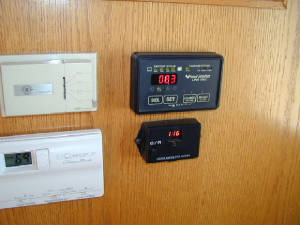
|
These are the minimum functions
you need, in my opinion. Anything else is optional, but you may feel like you need it. Personally, I like to know everything
that is going on, but realistically it is not required. For example, it is nice to have a monitor for the solar regulator,
but since there is really nothing to control (other than possibly equalization), it is really not necessary. You can see the
charge amps and voltage on your battery monitor. The only measurement that is
missing is input amps and voltage coming into the regulator. This is interesting if you want to see how much “boost”
you are getting from an MPPT regulator, or just to see how much current is lost in wire runs. My solar regulator display is
behind a door, and I rarely look at it.
You need to place the displays where you will see them. They are no good hidden away. Our displays in our current rig
are right inside the door, where they are easily seen. In another rig they were in the hallway to the bath. You will find
you will refer to them often, especially when you are learning the operational characteristics of the system.
In my opinion, and it is shared with many industry experts, you absolutely need to measure cummulative amp hours of your
battery bank. There is simply no other way to effectively know the current state of the bank. If the instrumentation
that is available for the inverter does not provide for this, then you need to augment it. If you are going to augment your
inverter monitor/control, then buy the cheapest control panel available for the inverter (making sure that it allows control
of all functions). Augment the control functions with monitoring functions provided by a TriMetric TM2020 monitoring system.
This provides all the monitoring functions you will need for your entire system, and is commonly available for around $150,
including a 500 amp shunt. You can check out the TriMetric at Bogart Engineering: http://www.bogartengineering.com/. You can buy the TriMetric at: http://www.solarseller.com/. If you want to monitor more than one power source individually, check out the new Pentametric battery monitor
from Bogart. It can monitor 3 charging sources at once. But it is not cheap. Don't view the purchase of the TriMetric
as spending an "extra" $150. If you can not determine the state of your system accurately you will have continual problems
down the road.
On a 30 amp RV I would wire the inverter
in-line and power the entire load center. This makes installation simple and ensures that the circuits you want powered are
available, since all circuits are available when inverting. I definately would not bother with a sub panel.
On a 50-ampere RV I would add a sub panel if it was at all possible. There are so many advantages to this approach
that it makes it worth the extra trouble. This would permit you the flexibility of using a 30 amp inverter if you choose.
If a sub panel was not possible, or you choose not to go through the headache of installing it, I would use a 50 amp split-phase
inverter that allows for "in-line" installation.
An alternative to splitting the panel in
a 50 amp RV is to use the Xantrex RV 2012 line of inverters and wire the inverter in-line to the entire load center. The 2012 allows you to pass both legs of the 50 amp shore power line through the inverter.
However, I don’t care for some of the other “features” of this inverter. Specifically, it has a constant
float stage that is not able to be turned off. Although it is more costly, I would favor the Xantrex RS3000, which also supports
both legs of a 50-amp service, and has none of the negatives of the RV series of inverters.
The small disadvantage of this implementation
is that the transfer switch in the inverter is handling a heavier load than if you used a sub panel. This small disadvantage
is outweighed by the ease of implementation, in my opinion.
|