|
| Electrical Center |
|
|
| Mounted on plywood in driver-side storage compartment. |
This article
describes the wiring center I added to Casper, my Volvo 610 tractor. Most of this is generally applicable to any truck - the
Volvo-specific parts are obvious.
The purpose
of the wiring center is to supply 12 /120-volt power for the cab, and to the trailer plug for the 5th wheel. This
article covers the basic how to's along with resources for parts and accessories. The wiring practices described here
are commonly used and are code conforming to the best of my knowledge, but this document should not be taken as electrical
advice - it is simply the way I did it.
My wiring
center is in the driver's side compartment, on the forward (left) wall. It is built on top of ¾ plywood, which was glued to
the plastic walls of the compartment with construction adhesive. Use of the plywood simplifies installation of components
and permits use of cheap, commonly available fasteners without penetration of the compartment walls. I painted the wood black before installation - this provides a more pleasing appearance. To protect the terminals and wires from shorts and damage, two plexiglass panels cover the appropriate
areas of the walls. This prevents cargo in the storage box from impacting the wire center.
The plexiglass is mounted with ¼ x 3.5 lag bolts through ½ plastic pipe used as standoffs. The area over the inverter
is not covered to ensure proper heat dissipation. The wire center is shown in
the picture above without the plexiglass panels in place. The perspective is looking forward from the rear of the truck.
All wiring
is fed into the compartment from a 3" x 1" hole in the floor. The easiest way to do this is with a 1" drill bit - drill a
hole at each end of the cutout, and use a Dermel tool with a cutting blade to connect the holes. The hole is a little crowded - you may want to consider a slightly larger hole.
Trailer Light Converter
The trailer
light converter provides power and signals to the 5th wheel. You need the
converter because a semi-trailer has separate brake/turn signals and the RV trailer has combination brake/turns. The
trailer connector lines you will tap in the tractor have to have the signals modified - the converter is what does this. Using
a converter properly combines the signals, isolates the tractor from the trailer electricals, and is self-powered so you can
not overload the tractor circuits when you add more lights to the trailer. You can wire the trailer directly off the tractor
tail lights, but this is a bad idea. It will increase the chances of future problems.
I used a Hoppy Model 46255 converter to supply
the appropriate signals. This is a powered converter - the advantage is
that it isolates the truck electrical system from the trailer, preventing any shorts in the trailer from impacting the truck.
If you have a lot of lights on your trailer (or expect to add them) you might want to use the Hoppy
46365. This converter can handle 8 amps. The converter is the gray box directly below the inverter. Look in the Resource Listing section for sources for the Hoppy.
The inputs
to the converter come from the existing green Volvo trailer feed wire, which was originally terminated behind the cab. This
was disconnected and moved into the storage box, through the hole in the floor. Turn signals and brake light feed were picked
up from the original trailer connector. The brake light signal was fed forward
(with a 14-gauge wire) into the cab to act as the brake signal for the Prodigy brake controller. It was easier to pick the brake signal up here than to find the brake signal in the cluster of wires in
the Volvo fuse center, and since you have to run a wire back from the controller anyway, it was no additional work. The braking output from the Prodigy is returned on a 10-gauge wire to the wire center, where it is soldered
to the new trailer connector line, which then runs to the rear of the truck. This brake line feeds 12v power to the trailer
braking system and needs to be at least 10 gauge to minimize voltage drop. Any connection in this line needs to be soldered,
or you will loose too much voltage.
I used
a Prodigy controller, which works well. If I was to do this over again, and had more time, I would consider the Hayes-Lemmerz
air-over-electric proportional controller, and the BrakeSmart controller. Most of the wiring would be the same except for
picking up the brake line signal. The major difference is that the H-L controller taps an air line to give you true
proportional braking with the air brake system of the truck, instead of using the electrical brake signal. It uses a
mechanical servo tapped into the air line that directly detects the amount of brake application. The BrakeSmart also taps
the air line, but detects brake application electrically. It is a more sophisticated design than the Hayes, and is priced
accordingly. The best place to pick up the signal for the BrakeSmart is in the "stop" air line, behind the instrument panel.
When I change controllers I will move to the BrakeSmart. Both of these controllers allow the Johnson Bar (the handle
on the dash) to be used for trailer braking. You can get the Hayes at http://aftermarket.hayes-lemmerz.com/html/air_actuated.html and the BrakeSmart at Dr. Performance http://www.drperformance.com/brakesmart.html. Mark Bruss has a good BrakeSmart installation article on his website at http://www.dmbruss.com/RR_BrakeController.htm. Emery Nash has a similar installation article on his picture site: http://www.webdoms.com/rving/brakesmart/index.html
For the BrakeSmart you need the following: 78010-5 Air Adapter kit, price
160.00;
78001 Controller, price 295.00. The phone number is 1-877-338-7373.
| Black is Stop, Orange is Park air lines |
|
| Photo by Mark Bruss, all rights reserved |
| BrakeSmart Transducer T'ed into stop light line |
|
| Photo by Mark Bruss, all rights reserved |
| Overview of Trailer connector |
|
|
The drawing
on the left shows an overview of the converter wiring. A detail drawing of the wire breakout (courtesy of Doug Simpson), can
be seen at Electrical Photos. An even better drawing is on the web site of Mark Bruss: http://www.dmbruss.com/RR_EW_TrailerWiring.htm. It shows the logical connections between the existing Volvo trailer cable, and the new trailer cable being added. I mounted all of my connections in the storage box. Mark, Doug and I all used barrier
strips to attach the wiring. This has several advantages: 1) it allows you to move the wires around, if you get them wrong
the first time 2). it makes for a neater installation 3) it allows you to add auxilliary lighting (like LED stop/turns) on
the rear of the truck cab and keep it isolated from the tractor system. Make sure you rub some oxguard onto the
wires before crimping on the terminals.
Wire Runs
All of
my wires run from the storage box, down through the floor, and then forward under the cab. They are strapped to the existing
wire bundle that is attached to the frame. They re-enter the cab just forward of the drivers seat, just inward of the removable
floor trim plate through several small holes drilled in the cab floor. They proceed forward to the front of the truck under
the floor mat, and from there either up to the top of the dash, or through the dash, as appropriate to their function. Some
wires run along the top of the dash down by the defroster outlets in black split loom.
You don't see them in that position. These wires are the camera wires for my backup cameras, and the telephone cable
that controls the remote On/Off for the inverter. The brake signal (input) and return (output) wire from the Prodigy controller
are run inside the dash to the controller which sits just to the right of the drivers right knee.
You could
also run the wires forward into the engine compartment and bring them through the firewall through a grommet. I found it easier
to bring them in at the door jamb.
The 120 volt AC line that feeds the receptacle on the dash runs
on the opposite side of the truck routed under the mat in a similar fashion, except that it comes through the rear of the
storage compartment, behind the refrigerator (which sits behind the passenger seat), and then under the floor mat. I ran the
120-volt power on the opposite side of the truck so that its proximity to the camera line would not cause interference.
The 12-volt System
The wire center is supplied with 12-volt power directly by the inverter cables. The inverter cables terminate in distribution hubs at the wire center, which allows you to easily
tap power for various functions. All negative wires terminate directly onto the
negative distribution hub. There are no terminations to the chassis - this will prevent bad grounds in the future.
Just to
the left of the inverter is a small 12-volt fuse center. I aquired it from Wrangler, but you can find similar fuse centers
at good auto parts stores. Blue Sea makes a very nice fuse center with either a 6 or 12 circuit capacity. This has a
negative bus incorporated into it. The part number for the 12-position is 5026 (http://www.bluesea.com/product.asp?Product_Id=30990). My fuse center currently contains the Hoppy converter fuse, a fuse supplying a relay for my bed-mounted
backup lights, and a fuse for the 12-volt supply for the cameras. The backup lights are tapped from the tractor cargo light
switch, so when I activate the light on the back of the cab, the lights built into the back bumper also come on.
You can
add a negative 12-volt buss bar if you need one. Use a buss bar from an AC load center. These are available in the electrical
section of Home Depot or Lowes, and are used to add neutral and ground busses to load centers. Just screw it to the
plywood and you are ready for hookups. Use a neutral lug and 4 or 6 ga cable to tie it to the distribution hub. You could
buy a negative buss bar from a specialty catalog - these have the advantage of having a post to tie in the negative feed line.
They also cost upward of $99, depending on what you get.
Future
expansion of the system is much easier with the fuse center in place (I have learned this the hard way).
In the
cab, the Prodigy controller is supplied with 12-volt power from the distribution hub on the firewall, directly above the steering
adjustment pedal. Ground for the Prodigy is tapped directly off the battery, following the instructions for installing the
Prodigy. Alternatively, you could tap the negative post behind the steering adjustment pedal, but the Prodigy instructions
are specific about tapping the battery directly. Both the ground and the positive
are 10 gauge wire - overkill, but I had it.
The new
trailer wire harness is supplied with 12-volt power from the distribution hub in the storage compartment. Typically, you would
tap the output of the alternator to supply the trailer line. You would use a battery isolator or a solenoid to separate the
banks - really only required if you keep the trailer and truck plugged together for long periods. If you really want to get
fancy you could use a "smart" charging switch, or a cross-charge regulator in place of an isolator or solenoid. This would
ensure that both the truck and trailer battery banks get a full charge off the alternator. If you don't use a "smart" charging
switch then the alternator will shut down when the first battery bank reaches the cut-off voltage of your truck regulator.
This will leave the other bank (typically the trailer bank) without a full charge. NEVER use a battery A/B/Both switch. These
just cause problems and if not used correctly can cause a system-wide electrical surge (if you switch it wrong while
the alternator is running) that will burn out your alternator diodes and/or other truck electical components.
In my
application these are all unnecessary. Since I have a large solar system (480 watts, 29 amps), I find that satisfactory for
my trailer battery bank charge. I only want access to 12-volt power at my trailer plug in order to run 12-volt appliances
(like a 12-volt water pump for pumping water from the truck to my trailer when boondocking). You will probably want to tap
your alternator output if you depend on the tractor to charge your trailer battery bank. Using the tractor battery bank as
the charge source for the trailer bank will result in the trailer bank never being fully charged.
On the
dash behind the CB radio holder I added a three outlet 12-volt accessory receptacle. This is handy for the GPS, etc. This
is permanently tapped off of the CB power point, from behind.
[A side note on the Volvo electrical monitor:
Many Volvo's have an electrical monitoring system designed to cut off power to various electrical items when battery voltage
falls below a designated threshold. An alarm goes along with this. On my Volvo, along with many others, this alarm would go
off even when voltage was "normal". In doing the work above, I discovered that the alarm was grounded to the rear of the power
center. Removing the ground wire stopped the alarm, and after a year or more does not seem to have any side effects. You may,
or may not, have the same wiring set-up.]
| Electrical Center Schematic |
|
|
You have a choice to make when you design
your 120-volt system. First, you can build a minimum system that meets your electrical needs. Most people only run a
refrigerator, occasionally use a microwave, and TV/satellite/DVD. The electrical requirement to support these devices
is minimal, especially if you use an LCD TV. So you really don't need an expensive or fancy system. Figure out your electrical
requirements by checking your devices for their power requirements; add up the wattage of all your devices that will run at
the same time. Add at least 40% to that and you know what size inverter you need. Typically, that would be 1200-1500 watts,
or less.
| Inverter/Charger Combined - with auto transfer |
|
|
The second
system is more sophisticated and permits more future expansion. It includes a larger inverter that incorporates
a charger and autoswitch. This permits you to expand the system to include a separate house battery bank, and to run higher-powered
devices for longer periods of time. This system approaches the capabilities of an RV system typically used with a solar setup.
The advantage of using the inverter/charger is that the autoswitch capability makes your 120-volt wiring much simpler. It
also costs significantly more!
I chose to go
the lower-cost route. Mainly because I do not envision using my truck as an RV for long periods of time without shore power
hookups. So my 120-volt inverter needs directed me to the lower cost inverter. This drove the rest of the electrical design.
I will describe the details of my implementation, but I have also included a schematic and details of the more sophisticated
implementation. Mark Bruss chose to use a high-powered inverter with his Volvo 770. You can see the details of his electrical
center at http://www.dmbruss.com/
The inverter
I used is a Xantrex XPower 1200 (1000 watts, continuous) with the optional remote
control. I purchased this online, through www.buy.com . At the time, they had the best price
(around $170 for both). I chose the 1200 because the highest power appliance I intend to power is a 600-watt microwave, and
this inverter has adequate power to do it. There is also an XPower 1750 (1500 watts, continuous) available; it uses the same remote control.
If you
want an integrated inverter/charger/transfer switch then the Tripplite APS2012 would be a good choice. They run around $600
online; you will also want the $105 remote switch. The integrated inverter/charger/autoswitch costs more, but makes the
wiring a little simpler.
Ideally,
any inverter you choose should be direct wire (for both AC and DC) and should have a remote on/off switch. Direct wire for
the AC output circuit simplifies the wiring to your house loads. If your inverter has outlets, most likely all of the
rated output is available from any of the outlets. Just use a 12 ga extension cord (cut to the appropriate length, or a direct-wire
plug) to supply the 120-volt power to either your 120-volt junction box, or loadcenter.
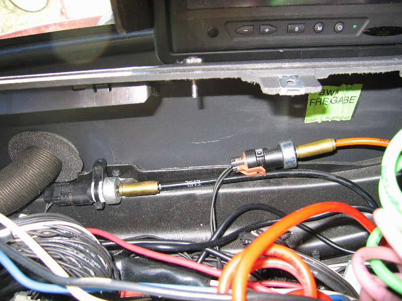
The remote on my inverter (and most of them) uses a 4-wire telephone cable. It attaches to the back
of the inverter. The control panel on mine happens to be the same height and
brushed aluminum finish as the Eaton autoshift display, so I removed a screw from the Eaton panel and mounted the remote right
on it. If you don't know differently, it almost seems like it belongs there.
[A note
on inverter technology. All the inverters above are modified sine wave. You may hear that using anything but a pure
sine wave inverter will cause interference problems with TV's or that certain devices won't run at all. While this is
certainly possible, depending on the device, modern modified sine wave inverters run almost all devices "cleanly". I
would not hesitate to use a modified sine wave inverter for everything except very specialized applications. Some TV's
will not work with modified sine wave - but I have never seen one, and I have installed many inverters in both RV's and
vehicles. Oxygen concentration equipment, laser printers and certain battery chargers all need pure sine wave. Almost
all other devices work fine on modified sine wave.
Microwave
ovens will run at reduced output on all inverters, so you simply program more time into them. We find it is best to run microwaves
on "high" only. Microwaves of all varieties are sensitive to the DC input voltage. Less DC voltage, less
cooking. This is true even though the AC output voltage of the inverter is held fairly constant. Don't plan on cooking extensive
meals with your microwave - it is best used for re-heating only.]
| DPDT 30 amp relay |
|
|
| Used to auto-switch to shore power |
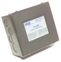
| Iota 30 amp transfer switch |
|
My inverter is mounted upside down
for access to the lugs. To the right of the inverter is a 30 amp DPDT relay with a 120-volt coil. Any good electric supply
house should have them. The relay takes as input the 120-volt inverter output and the shore power line. The shore power also
feeds the coil, so when shore power is available it will always be favored. A
cover is available for the relay, and I recommend spending the extra $20 to get it.
I covered the entire area with a plexiglass panel so the power lugs are protected, but the relay cover would probably
be better. The relay cost $27 without the cover.
An alternative to "building your own" transfer
switch from a relay is to simply buy a transfer switch. Iota makes a good one at a reasonable price. A 30 amp version is $55
at http://www.solarseller.com. If you are going to buy the cover for the DPDT relay like I used, just buy the transfer switch instead; you will be better
off.
Of course, if you are using the higher-priced
inverter/charger with an autoswitch capability you will not need to set up your own transfer switch - it is built into the
inverter.
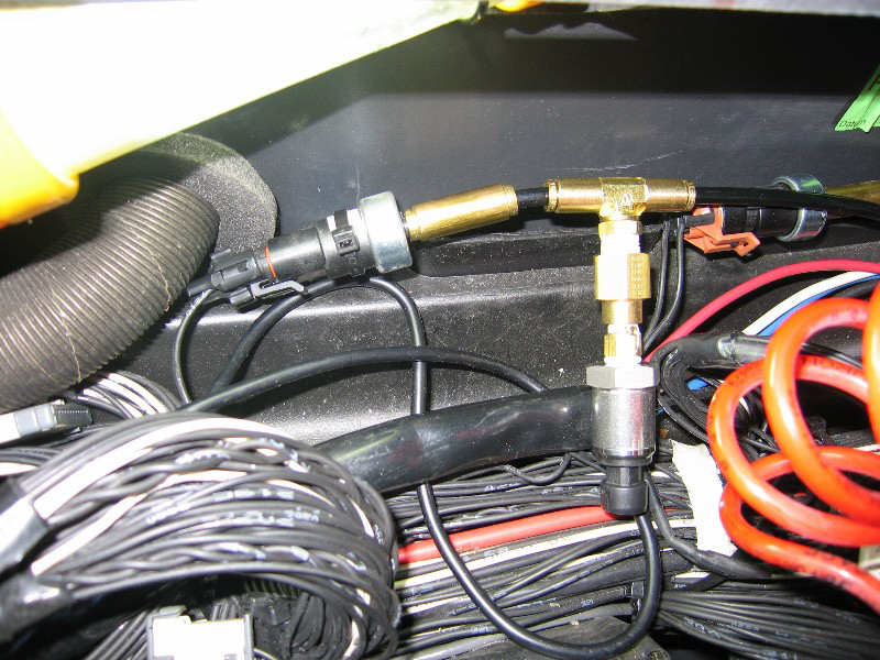
| Block heater used as Shore Power input |
|
|
| Rated for 20 amps |
The shore power
connector is shown to the left. In my case, Larry used a 20 amp block heater connector when my truck was converted, which
was adequate for my loads (I plug into 20 amp power sources, either on the side of my RV, or the receptacles in the RV power
post). If you supply a 30 amp shore power input, use the appropriately rated shore power connector. A twist-lock marine connector
would be a good choice - see http://www.boatersland.com for a good selection of parts. Even if you use a 20 amp connector
like on my truck, the wire from the shore connector to the 30 amp relay should be 10 gauge, in order to support a full
30 amps. If you wire it this way from the outset, you won't have to upgrade this later if you decide to increase your power
input and switch to a 30 amp connector.
[A side note on plugging your truck directly into an
outlet on your RV. If you do this, you need to figure the effect it has on total RV power draw. For example, if
we plug our trucks block heater into the outlet on the side of our rig (instead of directly into the RV park power outlet),
we can easily trip a 30 amp breaker. If you are using an electric heater in the RV, and a few other things, the 12 amps that
the block heater draws can push you over the 30 amp rating.]
If you store your truck for long periods of time and want to keep your batteries
charged via your shore power hookup the simplest way to do it is to use a 120-volt trickle charger. Wire the feed for this
onto the relay where the shore power line attaches. Make sure you maintain polarity if the charger requires it. Wiring
to the input side of the relay will ensure that the charger only draws its power from the shore power
hookup, never from the inverter. An alternative (and maybe better) wiring strategy is to put a receptacle into the shore power
line inside the compartment, but before it goes to the relay. Then, simply plug the trickle charger into the receptacle. The
output from the trickle charger ties directly to the distribution posts - cut the battery clamps off, and replace them with
ring terminals. You want to make sure you tap into power before it enters the inverter - you don't want to
try to charge batteries with the inverter output from the batteries. Again, this is not required if you use the inverter/charger,
because the charger is built into the inverter.
In my installation the output from the transfer
relay goes to a 4 inch electrical junction box where it is split into 2 lines. The first goes to feed the refrigerator
and microwave. It is routed through the back of the storage compartment, wire wrapped to the existing wire bundle. Instead
of mounting a receptacle in/on the passenger-side storage compartment, I used a direct-wire multistrip, which I mounted above
the blower inside the passenger-side storage compartment. The plugs for
the refrigerator and microwave enter this compartment through a hole behind the refrigerator. This was easier and just as
effective as a wall-mounted receptacle. I specifically did not want a receptacle because I wanted the refrigerator to be flush
against the side of the storage compartment - with a receptacle the plug would have interfered with flush mounting. I also
did not want to see any cords in the cab area.
| 120-volt Loadcenter |
|
|
| Use with 30-amp shore power input |
Instead
of using a junction box to originate your 120-volt wire runs, you can alternatively put in a 120-volt loadcenter. If you use
the higher-powered inverter/charger, or have a 30-amp shore power input this will be required, because you will not have
adequate overload protection on your truck circuits without it. (If you restrict yourself to a 20 amp input you have properly
sized breakers at the power source. With 30 amp input your truck wires could become overloaded, since the source breaker
is 30 amps and your internal wire runs are probably wired with 12 or 14ga.) Size the loadcenter to support the number
of circuits required for your application. Like the junction box, the input to the breaker box (loadcenter) is the output
from the transfer relay (either the separate relay, as in my installation, or the relay inside the autoswitching inverter/charger
which just passes through shore power when it is detected). A schematic of the breaker box is shown above.
The second
120-volt line follows the first one through the storage compartment, through the hole, behind the refrigerator, under the
floor mat, and up onto the truck dash. There it terminates in a standard shallow duplex box (painted black). I use this for
my laptop computer (no, I do not have a 12-volt adaptor for it).
[A note about the refrigerator. I decided not to use a 12-volt
fridge. Mainly because of the cost - over $500. I found a small Whirlpool (Model
EL02PPXMQ) 120-volt energy efficient refrigerator for $58 at Lowes that only draws 1.1 amps AC. The battery bank can easily
sustain the 12 amp DC load this fridge places on it (remember, you loose power during conversion). I don't run it that much
when not on shore power, or driving. The additional advantage of this refrigerator is that its width permits it to fit between
the seat belt mount and the bed, and its height permits the passenger seat to recline some. After living with this refrigerator
for two years I am still very pleased with it. It cools down extremely fast, and I can leave it on for days at a time on the
inverter with no apparent effect on the battery bank.]
Grounding
Ground the inverter following the manufacturer's instructions. If you are using an inverter with a transfer switch, the
AC ground input and output lines have lugs or ground wires inside the inverter to attach to. If you are using a small
inverter and its inbuilt receptical then the AC output line ground is simply part of the wire you plug in. Internal to the
inverter, it is likely bonded to the chassis.
Almost all larger inverters have a separate external chassis ground lug on them. This goes directly to chassis ground
- NOT to the DC negative bussbar, or the battery ground, or the AC loadcenter. Usually, 8 AWG wire is sufficient, but the
inverter manufacturer will specify the wire size depending on the inverter size.
The AC output from the inverter goes to some sort of AC distribution panel (or junction box, if not protected by breakers).
In the case of smaller inverters without an inbuilt transfer switch you will run it through an external transfer switch or
relay to control shore power selection.
If you are using an external transfer relay like the Iota, follow their instructions on grounding hookup. There will
either be bonding terninals inside the transfer switch, or they will specify the method that the grounds be bonded to
each other.
If you are using a DPDT relay, like I did, then bond all the grounds together and crimp them. If you use a wire nut,
make sure you tape it. You can see this in the picture of the DPDT relay (follow the green wires). Establish a chassis ground
either where you merge the grounds (add an extra chassis ground wire to the three existing ground wires) , or at the
AC distribution panel or box, depending on how you prefer to wire. When not connected to AC shore power the chassis ground
will offer some protection, but it is nowhere near as good as an earth ground. When on shore power, ground will flow back
to the utility ground.
Adding a Separate House Battery Bank
If your electrical needs are great (or
if you think they are) you have no alternative but to add a separate house battery bank to your vehicle. We are talking about
electrical usage while not connected to any charging source – e.g. the engine is not running, and you are not hooked
to shore power. The starting battery bank will suffice for occasional boondock use, but is not designed to be deeply cycled.
If you deep-cycle your starting bank more than a couple of times, you will be buying batteries.
Adding a separate house bank solves the problem of overburdening
your starting bank, but creates its own set of issues – mainly cost and complexity.
A lot of cost, and a lot of complexity. In order to have a properly functioning house bank you need to have a charging
source for it. Deep cycle batteries are more sophisticated than starting batteries and require a multi-stage charger in order
not to “kill” them over time. Using just your alternator with its stock regulator will result in a constant undercharge
– remember, that alternator/regulator is designed to maintain starting batteries, which are rarely discharged more than
5%, and have a different charge curve than deep cycle batteries. Fortunately, if you are implementing a house bank you are
probably already using an inverter/charger which is designed to manage deep cycle batteries. So you will have a way of fully
charging your house bank when hooked to shore power.
Cables and Battery Connections
I always
build my own cables. First, it is cheaper and you get a better product. Second,
it is difficult or impossible to get the wire lengths and orientation of the lugs correct if they are built commercially.
It is
not difficult to build your own high-amperage cables, but you do need the correct tools and parts. For tools, you need a cable cutter that is capable of cutting at least 2/0 cable. Klein makes a compact
cable cutter that will work - available at electric supply houses and Home Depot/Lowes for about $25. This will cut 4/0 with
a little grunting. Believe me it is worth buying. If you decide not to use a
cable cutter you can cut the wire with a reciprocating saw or hacksaw - clamp it in a vice first. If you go this route you
will have ragged ends - use a grinder to smooth the edges out. If you don't you will never get them into the lug - the lugs
are pretty much the EXACT size of the wire.
You also
need a large crimper for the magna-lugs you will use. At the end of this section is
an example of a hammer crimper that works well. You put the lug into the anvil and whack it with a maul. The alternative to crimping is to solder the lugs. If you decide to solder I recommend Fusion lugs. These have solder and flux in the barrel of the lug. You stick the lug in a vice, heat it with a torch and when the solder melts insert
the wire. The problem with this is that it is often difficult to get the wire in, and you have to fool with it. Difficult
when you have a hot lug and limited time to get the wire in. I prefer to crimp.
Note that these
lugs have closed fronts, and are tin-coated for corrosion resistance. They are pure copper underneath. The lugs, crimper and
battery extension posts (see below) are available at www.solarseller.com, http://www.thesolar.biz, or at www.wranglernw.com. You will find it useful to call Wrangler Power (800-962-2616) and order their
catalog. They have high quality parts, regulators, high output alternators, isolators, lugs, 12-volt fuse centers, etc.
described in the catalog. Their website is very difficult to use. Solarseller has better prices than Wrangler, if they
have the part. If you can't find wire locally you can get it from http://www.weldingsupply.com. They have colored wire for a reasonable price.
You also
need an antioxident, which is used on the wires before crimping. This helps prevent
corrosion and decreases electrical resistance. Apply to the wires and rub in. Squirt a little into the lug before crimping.
You should put antioxident on all wires - no matter the size - before crimping. One brand name available at Home Depot/Lowes
is Oxguard.
After
crimping you apply an adhesive heat shrink tube (color coded, of course) over the lug. Once melted, the adhesive totally seals
the barrel of the lug and greatly minimizes future corrosion. You will probably have to mail order the adhesive heat shrink
tubing (either source, above).
You should
always use welding cable for high amperage cables, which is easily obtained at any welding supply house. Buy it uncut and
cut it yourself when building the cables. I bought 16 feet of 2/0 for my Volvo (for $28 including tax), and had several
feet left. I never use less than 2/0, at least for 1000 watts or more. On solar installations I generally interconnect the
battery bank with 2/0, and run 4/0 to the inverter, depending on the size of the inverter and the length of run. Of course,
on the Volvo, the battery bank is already interconnected. Unless you are using
a very large inverter, say over 2000 watts, and intend to pull large loads it is not necessary to rewire the Volvo battery
bank. Just use the appropriate size cable to feed the inverter.
Hooking
up the inverter cables is not difficult but there is only one correct way to do it. The positive feed originates
from one side of the battery bank, and the negative feed from the opposite end (battery 1 and battery 4, in my 4-battery system).
My negative feed comes off the left most battery, but you can do the opposite if you want.
Diagonally loading the bank ensures that all batteries are drawn down equally.
If you hook both leads to one battery - no matter which one - that battery will be supplying more of the load
than the others. Rub a little oxguard on the lug before bolting it down. You may have to drill the lug to a larger size, depending on the lug and the battery.
You might want to measure the battery terminal bolt size before ordering lugs.
| Inverter Fuse |
|
|
| Note battery post extension for fuse barrel to clear battery |
On the positive battery
terminal feeding the inverter you need to insert a fuse of an appropriate size - 25% larger amperage than your largest
load (or possible load) but also within the ampacity of the cable (this should not be a problem if you use 2/0 cable). Your inverter installation instructions should tell you the appropriate size. I use
Buss type T-JJS DC rated fuses. This prevents accidental welding or other catastrophic shorts. To get the barrel of the fuse
to clear the battery you need a battery extension post, otherwise there is not room.
Just bolt the lug to the fuse, and the fuse goes directly on the extension. Don't forget the oxguard. You can wrap
the fuse with good quality electric tape to minimize the chance of a short when using tools in the battery compartment. You
can also mount the fuse in a fuseholder. On vehicles this is often difficult to do and still keep the fuse within a (max)
of 18" from the battery. So I generally mount the fuse directly to the battery post on vehicles. On RV's I almost always use
a fuseholder, since there is usually plenty of mounting room. Either approach is acceptable.
[A note on main battery
fusing when adding an inverter: For the inverter/house system wire run you can fuse either the negative or positive line (at
the battery connection). It makes no difference electrically. I have described fusing the positive, since that is more "conventional".
In fact, Coast Guard regulations actually require it to be fused this way (for you boat guys). Fusing the negative line has
some advantages - mainly that you do not have to protect the fuse from shorts. I have my negative line fused - do it the way
you feel comfortable with. Regardless of the main fuse method you use, you still have to fuse each individual component
circuit in the truck, and these are always done at the positive line - it is typically more convenient. The
discussion here relates to the main inverter line fusing.]
On my Volvo I ran the cables together (directly next to each other - you can
tie-wrap them together if you want) and then tie-wrapped them to the existing cable run along the frame, bringing them up
through the floor of the storage compartment to the distribution hubs. You can
twist them together if you want, but it does increase the length and I doubt you will notice any difference. Both methods
increase electrical efficiency and cut down on magnetic interference. I have installed over a dozen inverters this way, and
have never experienced any interference with other electronic devices.
Hints on Cable Building
When you go to build the
cables, build them one at a time - do not try to cut them all to length and then mass-produce the ends. You need to take into account twists and turns in the line - the lugs do not necessarily orient in the
same direction. I have found that if you put one lug on and then take the entire
cable bundle and lay the uncut cable out in its final position (or approximate it), then place the uncrimped lug on its bolt
and actually lay the cable across the lug you will get the exact length you need. Make sure to place an orientation mark on
the uncrimped end so you know the angle of the lug on the wire. Otherwise you
may find you have a very twisted wire because the lug is rotated into an inconvenient position. Repeat for each cable. Typically, you do not leave extra length in inverter-feed cables.
Every foot counts against you for voltage drop, so make the cable runs as short as possible.
| Inverter fuse - mount directly on battery positive |
|
|
| Crimper for Mega-lugs |
|
|
| Use a mallet to create crimp. |
| Cable cutters for up to 4/0 cable. |
|
|
| These will save you alot of time. |
|